Barrel Pump Components Explained: Construction, Design & Working Principles
Understanding Barrel Pump Components and How They Work
A barrel pump is a vertical, tube‑style transfer pump designed to safely empty drums and containers without tipping. You can review the fundamental operating principles in our barrel pump basics guide. Here we discuss how the design of the pump components, including the pump tube, drive motor, impeller, drive shaft, bearings, seals, plus the wetted materials, contribute to overall pump efficiency, performance and chemical resistance. The pump components define how efficiently fluid moves through the pump tube, and how the pump operates under specific hydraulic conditions.
Why Barrel Pump Components Matter
The pump design directly influences how efficiently it transfers liquids. Each component contributes to core performance factors such as flow rate, discharge pressure, suction, chemical compatibility and also long‑term mechanical durability. Furthermore, the design of the pump tube, impeller, shaft, seals and motor determines how reliably the pump can handle corrosive chemicals, flammable media, or high‑viscosity fluids under specific conditions.
Component design must prevent common problems such as cavitation, backflow, suction loss, or seal degradation. Precision‑machined internal parts maintain consistent rotational speed and minimise wear, which is consequently essential for high viscosity and ATEX applications. Correct selection of pump tube, impeller and seal materials directly influence chemical resistance and may prevent premature failure.
For a deeper look at how pump design affects performance in different applications, explore our barrel pump useful information resource.
Core Barrel Pump Components
1. Pump Tube Assembly
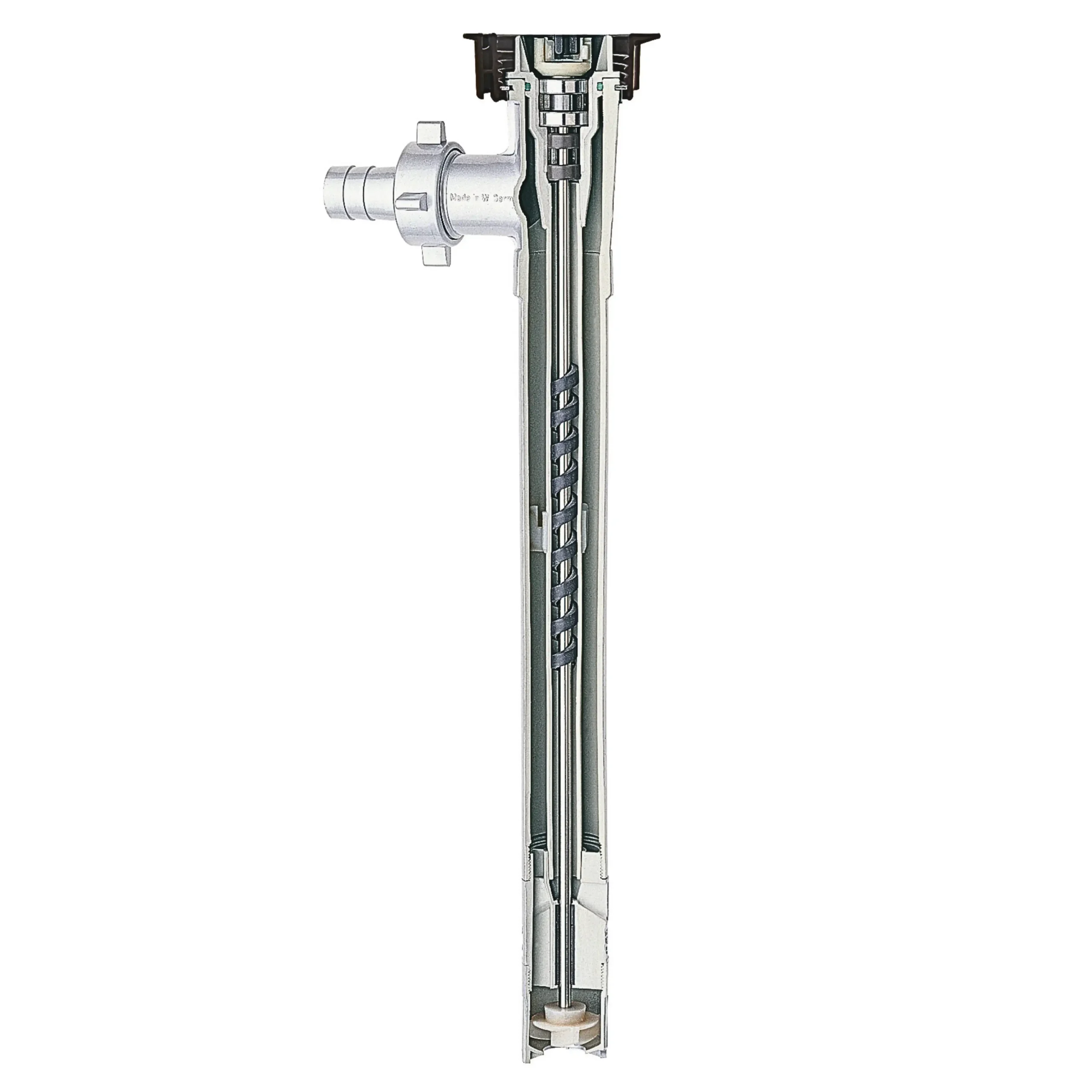
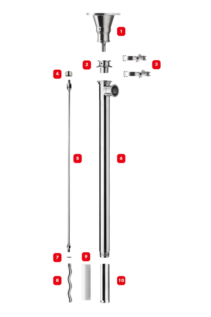
Firstly, the pump tube is the structural housing for all rotating elements. It contains the inner tube, drive shaft, bearings, seals and impeller in a tough, close-tolerance, packaged design that maintains laminar flow and prevents fluid turbulence. Tube lengths typically range from 700–1,200 mm to match container immersion depth, however, pumps up to 3,000 mm long are available for special applications. Furthermore, pump tubes are constructed from Polypropylene, PVDF, Aluminium, Hastelloy-C or Stainless Steel 316, with selection based on chemical resistance, liquid temperature and required discharge pressure.
2. Drive Motor
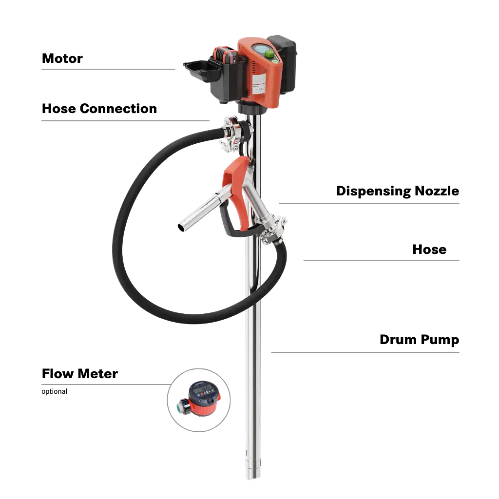
Secondly, the motor delivers rotational energy to the pump drive shaft. Motor torque directly influences achievable flow rate and viscosity handling. The most common design is a single-phase electric motor from 250 – 800 W in size. Pneumatic motors are also available. They are commonly used in ATEX-zoned areas and when handling flammable media. Cordless battery-powered motors are ideal for mobile operations, or pumping in remote locations where mains power is unavailable.
3. Driveshaft and Bearings
The driveshaft transmits motor torque to the impeller. Shafts are typically constructed from Stainless Steel 316 or Hastelloy C materials. Thicker diameter shafts minimise deflection and associated vibrations. The shaft is supported by precision bearings that maintain concentric rotation, reduce friction and resist axial load. The bearings and shaft are housed inside the inner tube, which provides the necessary support. Bearing size, design and materials directly influence service life – especially important when pumping abrasive or high‑temperature liquids. Bearing materials include brass, stainless steel and PTFE, depending on pump type.
4. Impeller or Rotor
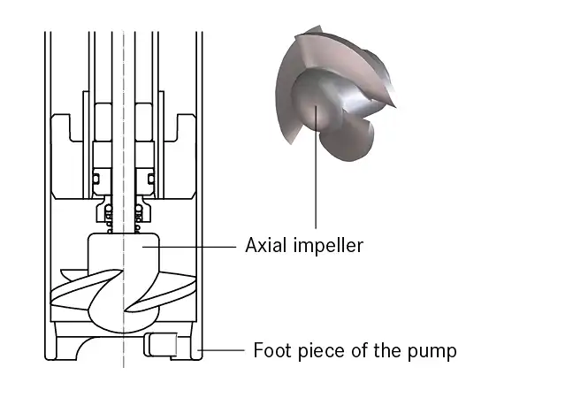
In general, centrifugal designs are suitable for lower‑viscosity liquids. Axial impeller designs deliver high flow rates; semi-axial designs deliver higher discharge pressure. The impeller creates a low-pressure zone at the pump inlet, helping fluid flow into the pump. Inlet geometry, blade pitch and clearance directly affect pressure development and pump efficiency. Alternatives include positive displacement designs such as progressive cavity and piston pumps. These create a high degree of suction – ideal for handling viscous media.
5. Foot Valve
Some centrifugal pump designs incorporate a foot valve at the pump tube inlet. Alternatively, a foot valve may be added as an optional accessory. Foot valves are designed to prevents backflow into the container. This will occur when the container becomes empty and air enters the pump inlet. The foot valve also minimizes drips and spills during container changeovers.
7. Seals and Gaskets
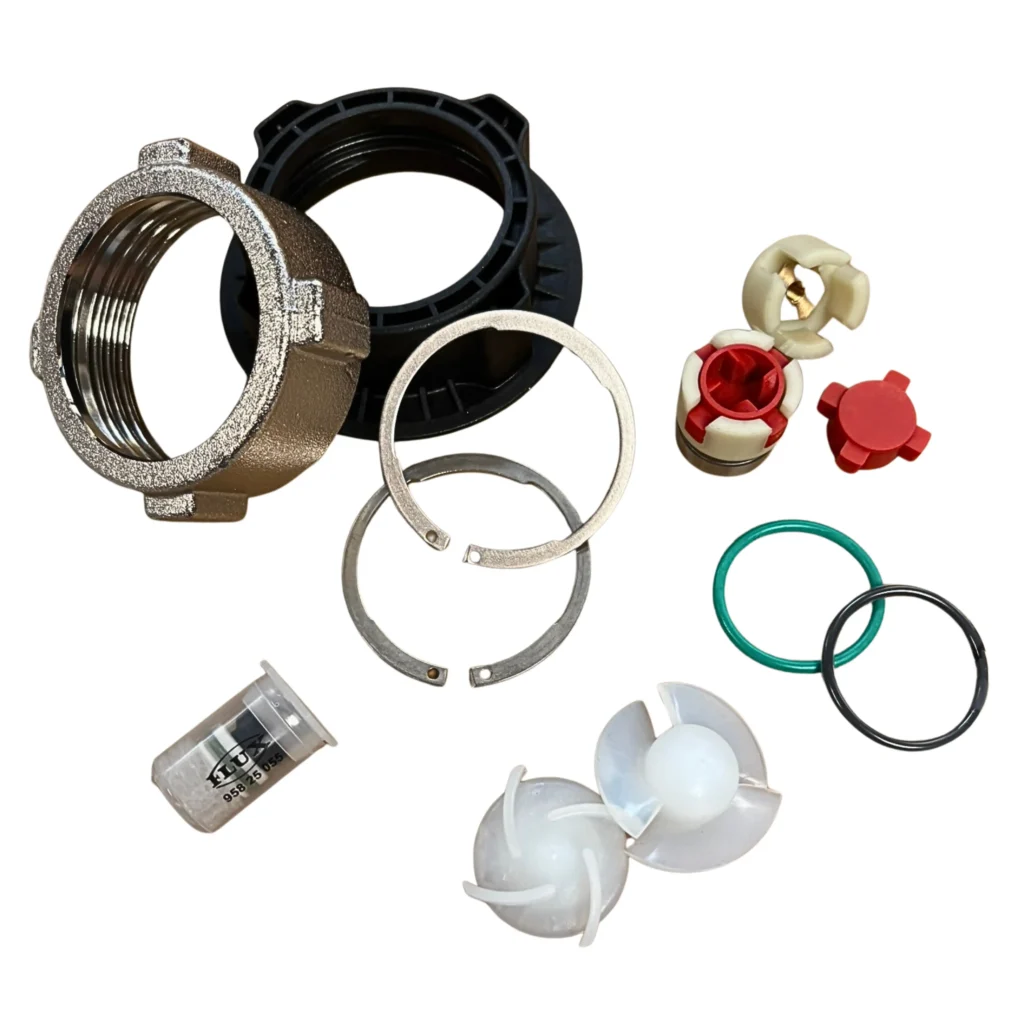
In a centrifugal pump, a mechanical seal positioned behind the impeller may be used to isolate rotating components from the pumped liquids. Mechanical seals protect the pump internals from corrosive or abrasive media and can enable pumps to deliver higher discharge pressure. O-rings are used to create leak-free seals between components. Therefore, o-ring materials must be selected to resist degradation or swelling.
Seal-less pumps still require vapour resistant o-rings to ensure potentially harmful fumes are not emitted. Reusable gaskets (commonly PE or PTFE materials) are required create an effective seal between similar rigid materials eg. the pump outlet and the hose connection.
How Centrifugal Drum Pump Components Work Together
1. Motor Activation
The drive motor delivers rotational torque to the drive shaft, initiating high‑speed rotation (typically 9,000 – 12,000 RPM). Components must remain stable during torque transfer to minimise damaging vibrations and maintain consistent impeller speed, especially when handling high density media.
2. Formation of Low-Pressure Zone
As the impeller rotates, it generates a low‑pressure zone at the pump tube inlet. This is not negative pressure i.e. vacuum; however, this low-pressure area still helps gravity push liquid into the pump inlet, thereby increasing efficiency. This is especially useful when handling higher viscosity products.
3. Fluid Movement
The impeller blades impart kinetic energy to the fluid, converting rotational motion into axial flow. Internal tube tolerances, impeller geometry and motor speed collectively determine achievable flow rate, pressure development and efficiency across different viscosities.
4. Controlled Discharge
Pressurised liquid exits through the pump tube discharge outlet, through a mating hose connection and into a connected hose or pipe. Larger bore hose ensures laminar discharge and optimal flow rate.
Material Selection and Its Impact on Components
Material selection is critical to the performance and longevity of barrel pump components, influencing chemical resistance, mechanical strength, temperature stability and also operational safety. Each material behaves differently when exposed to certain chemicals, high temperature and tough duty cycles. The four common pump body materials are:
PP – Suitable for many low concentration acids, alkalis and water-based chemicals. Its low weight and good corrosion resistance make it ideal for general chemical transfer, though liquid temperature is limited to 50 deg C.
PVDF – Highly resistant material suitable for concentrated, corrosive, high‑temperature acids, eg. Nitric and Sulphuric. Its high crystallinity provides excellent abrasion resistance and stability under thermal stress.
SS‑316 Ti – Ideal for solvents, oils, fuels, petroleum additives and food applications. Its Titanium content improves pitting resistance, thereby making it suitable for demanding industrial chemicals.
AL – Suitable for many automotive applications eg. transferring coolant, DEF, diesel fuel and also mineral oils.
If applicable, o-ring materials must also be selected carefully to ensure they are chemically resistant.
Furthermore, ATEX‑certified pumps in SS 316 Ti or Hastelloy materials are required for handling highly flammable liquids and use in explosive atmospheres. These pumps are designed to eliminate ignition sources and the risk of static electrical discharge, therefore ensuring spark‑free operation.
Incorrect material selection can lead to embrittlement, softening, cracking, or premature seal failure, consequently compromising pump integrity and operator safety.
Performance Factors Influenced by Components
Viscosity
Viscosity has a direct impact on how barrel pump components behave under load. Thicker fluids increase hydraulic resistance, requiring higher torque motors, progressive cavity mechanisms, or piston‑type designs to achieve stable, meaningful flow. Centrifugal impellers suit low‑viscosity liquids because they rely on free‑flowing media to generate pressure efficiently. They cannot create negative pressure ahead of the impeller, therefore as viscosity rises, impeller slip increases, reducing achievable flow rate and pressure.
Pump Stability
Tube length must be long enough to ensure full immersion and thus complete container emptying. If the tube is too short, air entrainment occurs and residual liquid will be left in the container. Excessively long pump tubes will result in the motor standing higher above the container, affecting weight distribution and stability. This is particularly relevant once the container becomes empty. Correct tube length ensures optimal inlet positioning without seriously impacting stability.
Flow Rate
Flow rate is determined by the choice of pumping mechanism, combined with motor speed, power and torque. Centrifugal pumps are limited by impeller speed and geometry, along with internal tube tolerances. Achievable flow rates typically span 10 -240 LPM depending on pump construction. Higher flow rates are not necessary for common barrel and IBC transfer applications. Flow performance also varies with fluid density, rheology and discharge head. If considering a progressive cavity pump for a high viscosity application, these pumps run slowly (approx. 200-1000 RPM), and typical flow rates range from 5 – 50 LPM.
Discharge pressure
Higher viscosity and higher density fluids require higher discharge pressure. Centrifugal barrel pumps can typically deliver max discharge pressure of approx. 3 Bar (depending on impeller design). Progressive cavity designs can deliver considerably higher pressure (up to 15 Bar), while piston pumps go far higher – over 100 Bar. Higher pressure is required to overcome pressure losses associated with pumping high viscosity, sticky or adhesive media over longer distances.
Temperature
Temperature affects both the mechanical stability and chemical resistance of barrel pump components. Elevated temperatures can reduce material strength, accelerate seal wear and increase the risk of chemical attack. High‑temperature fluids may require specialised seals, reinforced polymers, or stainless‑steel wetted parts to maintain structural integrity. Thermal expansion must also be considered to prevent binding or misalignment within the pump tube. This is especially important when considering pumps fitted with mechanical seals.
Maintenance of Barrel Pump Components
Regular maintenance ensures that barrel pump components operate within their designed tolerances and maintain safe, reliable performance over time. Mechanical wear, chemical exposure and thermal cycling all influence service life, so each component requires targeted inspection.
Inspect seals for wear – Seal faces and elastomers degrade with chemical exposure and increasing running hours. Early detection prevents leaks and cross‑contamination.
Flush the pump after use with corrosive or crystallising chemicals – Residual media can crystallise or polymerise, affecting impeller clearance and leading to bearing wear.
Maintain air supply quality for pneumatic motors – Clean, dry air prevents internal corrosion and ensures reliable torque delivery. Oil lubrication is not essential with all vane motors, but it will increase service life.
Replace brushes and bearings in electric motors when required – Worn brushes reduce RPM consistency and can cause overheating under load.
For deeper guidance on preventive maintenance practices, including vibration monitoring, seal checks and overheating prevention, explore our pump maintenance resource.
Optimising Performance Through the Right Barrel Pump Components
Barrel pump components ultimately determine how safely, efficiently and consistently a pump handles liquid transfer. Understanding the engineering behind each part – from the pump tube and impeller to seals and drive motors – allows you to specify a pump that delivers the longest possible service life. High‑quality, high-tolerance components reduce risk of leakage, minimise downtime and ensure reliable fluid transfer even under demanding conditions.
For deeper technical guidance, explore our FLUX pump resources or speak directly with our sales engineers to ensure you select the correct pump for your application.